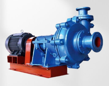
Causes and Solutions for Slurry Pump Motor Overload (High Current)
Date:
2025-09-17
Causes and Solutions for Slurry Pump Motor Overload (High Current)
Complete Technical Guide to Diagnosing and Preventing Motor Overload in Slurry Pump Applications
Motor overload represents one of the most common and potentially damaging operational issues in slurry pumping systems. When a pump motor draws excessive current, it not only increases energy consumption but also risks premature motor failure, unexpected downtime, and significant repair costs. Understanding the root causes of motor overload is essential for maintaining operational efficiency and equipment longevity in demanding slurry applications.
Understanding Motor Overload in Slurry Pumps
Motor overload occurs when the current drawn by the electric motor exceeds its rated amperage. In slurry pump applications, this typically happens when the pump requires more power than the motor can safely deliver. This condition triggers thermal overload protection devices and, if persistent, can cause insulation breakdown, bearing damage, and complete motor failure.
Diagnostic Table: Motor Overload Symptoms and Immediate Actions
| Symptom | Possible Cause | Immediate Action |
|---|---|---|
| Gradual current increase | Wear, buildup, or changing slurry density | Check wear components, measure density |
| Sudcurrent current spike | Blockage, seizure, or mechanical binding | Shut down immediately, inspect pump |
| Cyclical current fluctuations | Air entrainment or varying sump levels | Check submergence, inspect for air leaks |
| High current with low flow | Closed discharge, system restriction | Verify valve positions, check pipeline |
| Overload at startup | Mechanical seizure, wrong rotation | Check rotation, verify free movement |
Primary Causes of Motor Overload in Slurry Pumps
1. Hydraulic Overload Conditions
High slurry density: Exceeding design density significantly increases power requirements
Increased flow rate: Operating too far right on the pump curve increases power demand
Elevated system head: Higher than expected discharge pressure requires more power
Cavitation: Creates vibration and inefficient operation, increasing current draw
2. Mechanical Causes
Bearing failure: Increased friction requires more power to overcome
Misalignment: Between pump and motor creates additional mechanical resistance
Rotor-stator contact: Internal rubbing within the pump creates drag
Seized or binding components: Lack of proper clearance increases mechanical resistance
Worn wear parts: Excessive clearances can cause inefficient operation and vibration
3. Electrical Issues
Low supply voltage: Causes higher current draw to achieve same power output
Voltage imbalance: Between phases creates uneven current distribution
Motor winding problems: Degraded insulation or shorted turns reduce efficiency
Poor connections: Lugs, terminals, or connections creating resistance
Incorrect motor selection: Undersized for application requirements
4. System Design and Operational Factors
Impeller too large: Oversized for motor horsepower capability
Speed too high: RPM exceeding design parameters
Blocked discharge: Restricted outflow increases pressure and power demand
Incorrect rotation: Reverse rotation reduces efficiency but may not lower current
Packing overtightened: Excessive gland adjustment creates constant friction
Step-by-Step Troubleshooting Guide
1. Initial Assessment
Measure operating current on all three phases
Compare to motor nameplate rated current
Check voltage at motor terminals under load
Verify rotational direction is correct
2. Mechanical Inspection
Check bearing temperatures for abnormal readings
Verify alignment between pump and motor
Confirm free rotation when disconnected from power
Inspect wear ring clearances and impeller condition
Check packing or mechanical seal condition
3. Process Evaluation
Measure slurry density and compare to design specifications
Verify flow rate matches pump curve expectations
Check system head against pump capability curve
Inspect for pipeline restrictions or blockages
Review valve positions in discharge system
4. Electrical System Check
Test voltage balance between all three phases
Measure voltage drop from source to motor
Inspect connections for tightness and corrosion
Check overload protection settings and calibration
Perform insulation resistance test if available
Practical Solutions for Motor Overload
1. Immediate Corrective Actions
Reduce flow rate by partially closing discharge valve
Adjust slurry density if possible to lower concentration
Clear blockages in suction or discharge lines
Check and correct pump rotation if reversed
2. Mechanical Solutions
Replace worn components to restore efficiency
Realign pump and motor to specified tolerances
Replace failed bearings before catastrophic failure
Adjust packing to allow slight leakage as specified
Balance rotating assembly to reduce vibration
3. System Modifications
Trim impeller to reduce power requirements (if appropriate)
Adjust operating speed to match system requirements
Install variable frequency drive for better power matching
Review system design to reduce excessive head requirements
Add air injection to reduce slurry density in critical sections
4. Electrical Corrections
Repair or replace motor if electrical faults are detected
Correct voltage problems at the source
Balance phase loading throughout the system
Upgrade undersized cables causing voltage drop
Set overload protection to proper ratings
Preventive Maintenance Strategies
Implement these practices to avoid motor overload situations:
Regular current monitoring: Document operating amperage during normal conditions
Scheduled inspections: Check alignment, bearings, and wear components periodically
Density monitoring: Install density gauges to alert operators of changes
Vibration analysis: Detect developing mechanical problems before they cause overload
Thermal imaging: Identify electrical connections and motor hot spots
Training programs: Educate operators on recognizing early signs of problems
When to Seek Professional Assistance
Consider expert help in these situations:
Persistent overload despite troubleshooting efforts
Multiple motor failures in the same application
System design questions requiring engineering analysis
Complex electrical problems beyond basic troubleshooting
Safety concerns regarding electrical system integrity
Conclusion
Motor overload in slurry pump applications signals either mechanical problems, process changes, or electrical issues that require immediate attention. By systematically addressing potential causes—from slurry density changes to mechanical wear—operations can maintain efficient pumping performance while protecting valuable motor assets. Regular monitoring, preventive maintenance, and prompt response to current increases provide the best defense against catastrophic motor failure and unexpected downtime.
Experiencing persistent motor overload problems with your slurry pumps? Contact our technical team for professional diagnosis and solution implementation tailored to your specific operational challenges.

Keywords:
Related News
Why Is Your New Slurry Pump Underperforming?
2025-09-22


